Diagnostics & troubleshooting
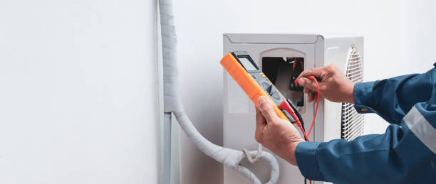
Symptom-driven testing: compressor amperage, capacitor, contactor, coil condition, airflow and refrigerant pressures. The goal is the failing part, not a parts cannon.
Ducted split · Heat pump · Mini-split
R-410A / R-454B · SEER2 · AFUE
Service & installation reference
System Overview
Air moves through a ducted system in a predictable path: condenser, line set, air handler, coil, registers. When one link in that path is undersized, blocked or out of balance, the whole house feels it. This page walks through the parts, the problems, and the process of getting a system right.
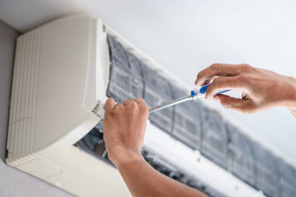
Fig. 01 — Exterior condenser array. Components labelled for reference.
01
How a ducted comfort system actually moves air
A ducted split system has two halves that talk to each other through a refrigerant line set. Outside sits the condenser: a compressor, a condensing coil, a fan, and service valves. Inside sits the air handler with the evaporator coil, the blower, the filter, and either a furnace or electric heat strips for the heating season.
Return air is pulled back through the return grilles, filtered in the air handler, cooled across the coil, and pushed back out through the supply registers and flex duct. When the duct system is undersized, leaky, or long, the room temperatures drift even though the equipment is working exactly as designed.
Equipment selection starts with a Manual J load calculation and a Manual D duct design, then the indoor and outdoor units are matched as a set. A two-ton outdoor unit paired with a three-ton air handler can short-cycle, freeze at the suction line, and wear the contactor out quickly, so matching is not optional.
02
Service lines for residential and light commercial equipment
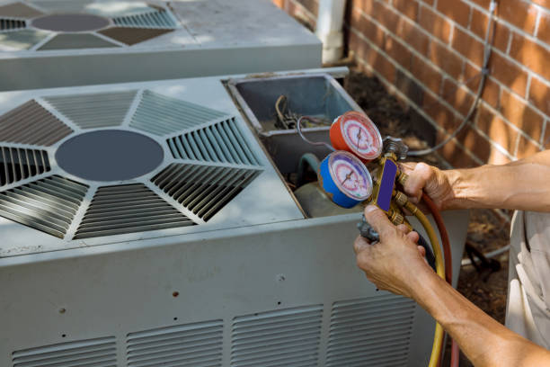
Symptom-driven testing: compressor amperage, capacitor, contactor, coil condition, airflow and refrigerant pressures. The goal is the failing part, not a parts cannon.
Nitrogen and electronic leak detection, repair of the line set or coil, then a recharge to the manufacturer’s charge specification with superheat and subcooling recorded.
Condenser coil washing, evaporator coil cleaning, filter and filter rack upgrades, and blower motor or capacitor replacement where airflow has drifted.
Reversing valve and mode control checks, defrost cycle behaviour, auxiliary heat staging, and charge verification on R-410A or R-454B systems.
Flame sensing, ignitor, inducer blower and heat exchanger inspection, plus blower motor, capacitor and contactor replacement.
Thermostat replacement and programming, low-voltage wiring repair, float switch wiring, and zoning or control changes where the equipment supports them.
Flex duct replacement, register and return balancing, manual damper adjustment, and duct sealing where leakage is cutting delivered airflow.
Head, line set and outdoor unit service, condensate routing checks, and multi-zone indoor unit commissioning.
RTU and AHU service including economizer operation, VAV box and actuator repair, filter upgrades, and TAB support after equipment changes.
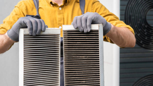
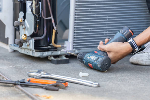
Fig. 02 — Service work at the unit: readings taken before and after the repair.
03
The six parts most service calls come back to
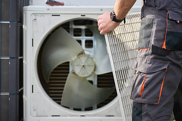
Compressor, condensing coil, fan motor and service valves. Its job is to dump indoor heat to the outside air. A dirty coil or a failing fan motor drives head pressure up and cuts capacity fast.
Watch for: high head pressure, warm case, tripped breaker, fan noise.
Insulated copper pair carrying refrigerant between the two halves. Standard line sets run 15 feet; longer runs need resized lines or a manufacturer’s allowance, and every line set must be nitrogen purged before it is opened.
Watch for: oil marks at the service valves, a lost charge, uninsulated sections.
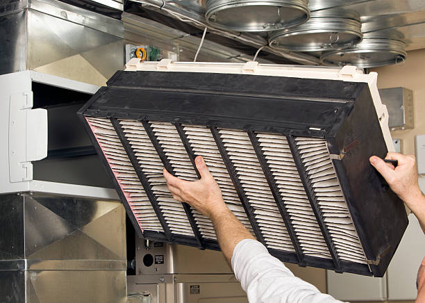
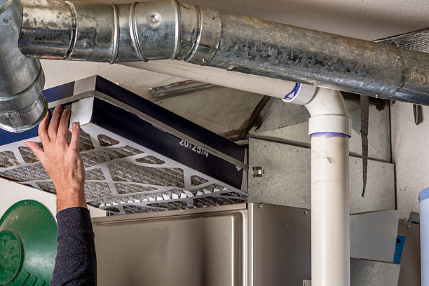
The indoor cabinet holds the coil, blower assembly, filter rack and humidity control. Static pressure across the unit should be measured before and after any repair.
Watch for: water on the floor, frozen coil, blower noise, weak airflow.
The heating half of the system: burner, heat exchanger, ignitor, flame sensor and inducer motor. Gas furnaces are rated by AFUE; electric units use resistance heat strips.
Watch for: repeated limit trips, short cycling, no heat, soot at the burner.
As the evaporator coil cools the air, moisture condenses and drains into the pan. The float switch shuts the system down if the drain line or pan ever stops draining.
Watch for: standing water, mineral build-up, musty smell, pan overflow alarms.
The control panel and thermostat talk over low-voltage wiring. A loose wire or a mismatched stage setting can stop heating, block cooling, or hold the system in one mode all season.
Watch for: no display, system ignoring setpoint, condenser running indoors.
04
Symptom, likely cause, first thing to check
Cause: low airflow or a low charge, both common.
Check: filter, blower speed, static pressure, then superheat.
Cause: a plugged condensate line or a failed float switch.
Check: pan, drain line slope, float switch wiring.
Cause: airflow starved at the evaporator coil.
Check: filter, blower wheel, coil freeze sensor.
Cause: low charge, low airflow, or oversized equipment.
Check: pressure readings, temperature split, unit match.
Cause: dirty coil, failing capacitor, or a leaky duct system.
Check: amperage, kW draw, duct leakage, filter.
Cause: flex duct compression, loose registers, or fan bearing wear.
Check: trunk lines, register clamps, blower wheel.
05
Six stages from load calculation to startup
Room-by-room load calculation, sun exposure, insulation, window area and existing duct layout recorded before anything is quoted.
Duct sizing, register layout, line set routing, and the indoor and outdoor unit match confirmed against the load.
Condenser pad or wall bracket, line set set and insulated, nitrogen purge, brazed joints, then air handler and furnace set in place.
Flex duct supported every interval, turns made in a radius, registers and returns fastened, condensate line pitched to an approved drain.
Evacuation to a verified vacuum, charge by weight or superheat and subcooling, then airflow, static pressure and temperature split documented.
Thermostat staged, filter and maintenance schedule explained, drain pan and float switch tested, and reading sheets left with the owner.
06
Seasonal items that keep a system predictable
07
Same physics, different equipment scale
 Unit spacing
Pad mount
Service clearance
Line set route
Unit spacing
Pad mount
Service clearance
Line set route
07 — Photo Feature
Airflow across a condenser coil drives how much heat it can reject. Clearance, coil condition and fan performance are why two identical units side by side can behave differently — and why the service tech starts at the outdoor unit before touching anything indoors.
08
Describe the system and the symptom, and the diagnosis starts from there